Propulsion System Summary
- Propellant load: 77 kg hydrazine
- 420-80 psia blowdown operation
- 12 Aerojet MR-103H 0.8 N thrusters
- 4 Aerojet MR-111C 4.4 N thrusters
- 1 PSI (P/N 80428-1) metallic diaphragm tank
Mission Design Requirements
Propulsion systems can have vastly different purposes. From small attitude correction maneuvers to boosting a launch vehicle in space, a propulsion system’s design is based on the mission requirements.
For New Horizons, the propulsion system does not need to induce a significant velocity change (ΔV) during the interplanetary trajectory. The launch vehicle provided the necessary characteristic velocity (C3 = 166 km²/s²) to escape Earth’s gravity and get to Pluto, and the Jupiter gravity assist provided a significant ΔV increase—a free lunch. The orbit injection was remarkably accurate, with a C3 injection error of only 0.0941 km²/s² (much less than predict 3σ of 0.4245 km²/s²). Figure 1 shows the amount of propellant saved due to this small injection error.
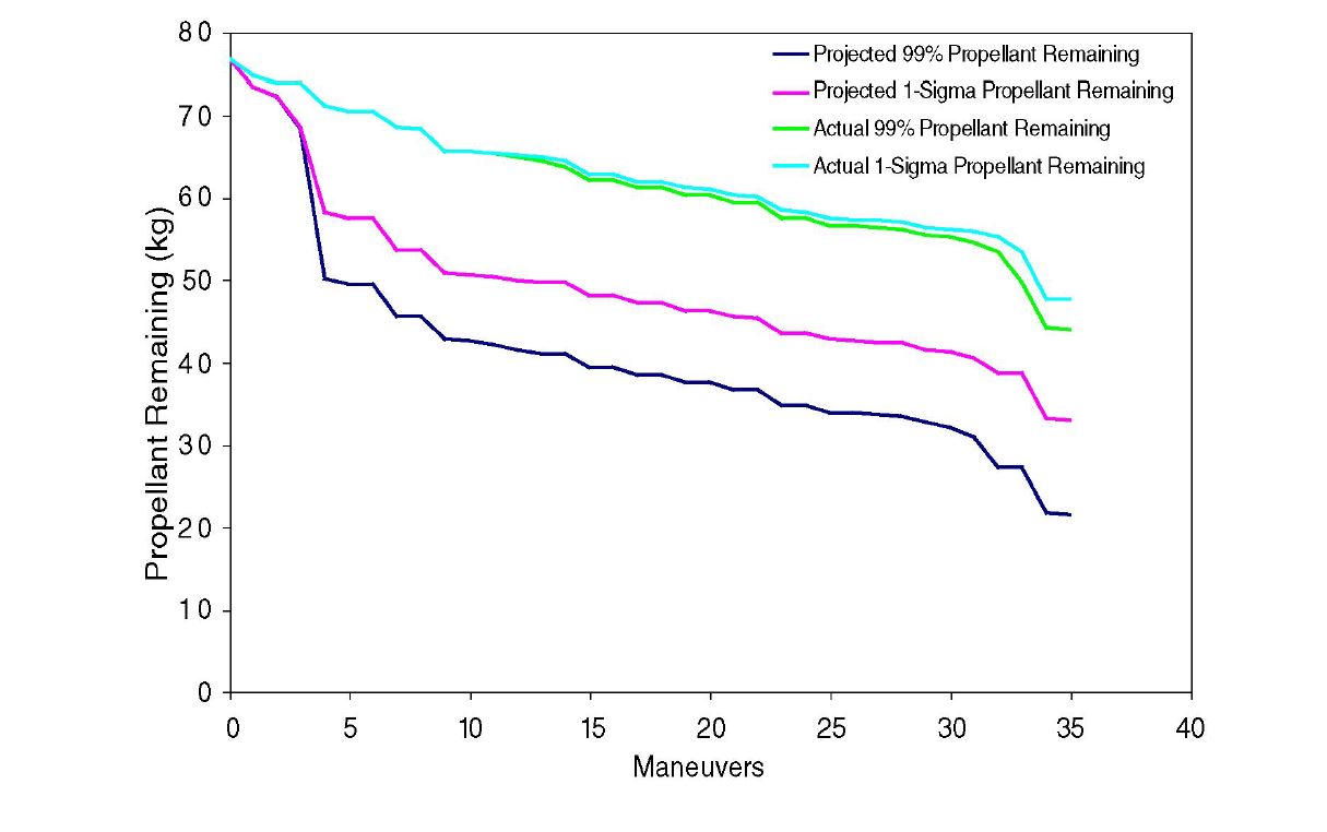
Figure 1
The propulsion system, however, has to provide statistical trajectory correction maneuvers, spin up/down maneuvers, attitude control maneuvers, slewing maneuvers for instruments, and a margin for both the primary and extended mission. The mission’s nominal ΔV budget is provided below, in Figure 2. From this budget, the propellant budget allocation can be determined (how much propellant is necessary to produce the ΔV required).

Figure 2
The mission had to meet a strict requirement of a mission success probability greater than 85%. Not only was the minimization of mass and power a top priority in the design of New Horizons, but so was functional redundancies in order to meet this success probability. Redundant components require more mass, but decrease failure rates. Mission lifetime and mass constraints drove the design to a blowdown hydrazine system that would serve as both the velocity control and as the only method of attitude control on board the spacecraft. Due to the power constraints of the mission, reaction wheels would not provide a viable control option.
One very important requirement was that at Pluto, the RALPH scan mode would require that the propulsion system be capable of delivering a minimum impulse bit no greater than 0.0066 N-s. This led to the selection of two candidate thrusters to meet the requirements of the mission: the Aerojet Minimum Impulse Thruster (MIT), and the Aerojet MR-103H thruster. However, at the time the program was proposed, the MIT thruster was still under development and awaiting qualification testing, whereas the MR-103H thruster was already qualified. In order to minimize the total schedule and cost risk, the MR-103H thrusters were chosen.
Important propulsion properties to consider during design:
- Cost and availability
- Physical properties
- Specific impulse and characteristic velocity
- Specific gravity
- Propellant stability
- Heat transfer
- Ignition and combustion
- Safety and environmental issues
- Materials compatibility
New Horizons’ Propulsion System Overview
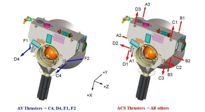
The New Horizons has a blowdown monopropellant hydrazine propulsion system, which includes 16 small hydrazine-propellant thrusters mounted across the spacecraft in eight locations, a fuel tank, and associated distribution plumbing and control valves. Twelve 0.8N thrusters, the Aerojet MR-103H, are used for pointing and attitude control, and the remaining four 4.4N thrusters, the Aerojet MR-111C, for course corrections. The individual thrusters are mounted on the spacecraft in eight locations: four groupings (called Rocket Engine Modules) and two independent thrusters. The locations of these thrusters, as well as their thrust vectors, are clearly depicted in the featured image at the top of this article and in Figure 5.
Even with the low-mass considerations, the propulsion system is not light-weight by any means. The whole system, including the propellant, comprised to nearly a ¼ of the wet mass of the spacecraft at launch. For interplanetary spacecrafts, the mass of propellant required for the mission typically exceeds the dry mass of the spacecraft itself. This is easily one of the most fundamental problems with propulsion systems.
On New Horizons, the spherical titanium tank had a hydrazine capacity of 113.4 kg. But, the launch vehicle’s payload mass restriction required less than 80 kg in the tank. So at launch, the spacecraft carried 76.84 kg of hydrazine. For the launch mass of 465 kg, this amount of hydrazine fuel load provides 397 m/s ΔV. It was estimated that there will be 44-47 kg of propellant (more than half of the tank) remaining after the Pluto flyby for the Kuiper Belt extended mission, corresponding to a ΔV capacity of 233-247 m/s.
Since launch, thousands of maneuvers have successfully executed. Given the mass and moments of inertia at launch, the ΔV propellant cost is approximately 4.9 m/(s kg). A change in spin rate of 5 rpm (i.e., the change from the nominal spin rate to zero rpm for 3-axis control mode) requires approximately 0.125 kg of hydrazine.
Propulsion system configuration
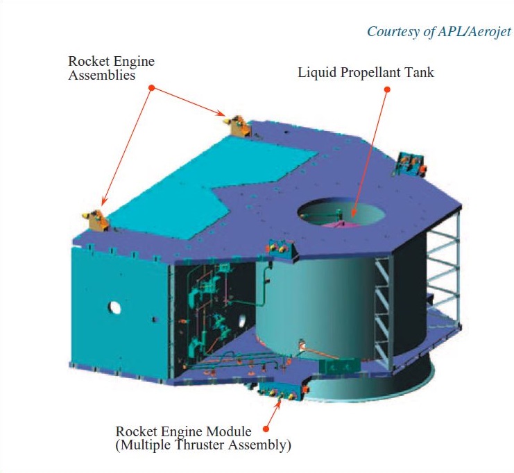
Figure 3
The propulsion system is mounted directly to the structure. Figure 3 provides a useful visualization of the internal structure and some of the propulsion system locations on New Horizons. The foundation of the spacecraft structure is a central cylinder located within the spacecraft main body. This single-piece, machined aluminum (7075-T73) ring forging is the focal point for the load path and, as such, is the primary load-bearing member of the spacecraft. This structure is also centered on the principal axis and the center of mass of the spacecraft. Directly attached to the central cylinder is the propulsion system fuel tank (centered within the cylinder). For reference, the instrument locations and more structural components are provided in Figure 3.
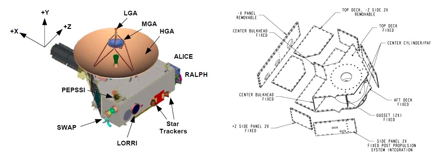
Figure 4
The placement of the tank is beneficial for a few reasons:
- At this location the variation in the fill fraction as the fuel is used has minimal impact on changes in the alignment of the spin axis.
- Since the tank is between the instruments and most of the electronics and RTG, the fuel further reduces the radiation effects of the RTG.
- Waste heat from the RTG and the electronics is used to keep the hydrazine sufficiently above the freezing point without significant use of makeup heater
Thruster coupling
Pairs of the 0.8N thrusters (each thruster from a different set) are usually fired to produce torques and control rotation about one of the three spacecraft axes. The one exception to the use of coupled thruster firings to control spacecraft rates is that of controlling rates about the spacecraft ±X axis during science observations, where uncoupled thruster firings are required to meet the maximum spacecraft drift rates allowed during this operation mode.
One pair of the 4.4N thrusters is aligned along the -Y spacecraft axis to provide ΔV for large propulsive events such as trajectory correction maneuvers (TCMs). The second pair of 4.4N thrusters is aligned to produce thrust along the +Y axis. These thrusters are rotated 45° in the Y–Z plane to minimize the plume impingement on the high gain antenna dish. The net propulsive effect of these thrusters is therefore reduced. They still provide the required redundancy and the ability to generate thrust in both directions without a 180° rotation of the spacecraft.

Figure 5
Because of these coupling thrusters, it was important to match the performance of each of the thrusters as closely as possible. This task was complicated by the fact that a single thruster can be operated with any of several other thrusters depending on the required torque to be imparted to the spacecraft. For example, from Figure 5 it can be seen that thruster A1 can be used with thruster B1 to provide torque about the +Y axis. Thruster A1 can also be combined with thruster D3 to provide torque about the +Z axis. Numerous thruster-to-thruster matching experiments were performed, including steady-state performance and pulse-mode performance comparisons, in order to determine the best possible thruster locations.
Thruster Specifications
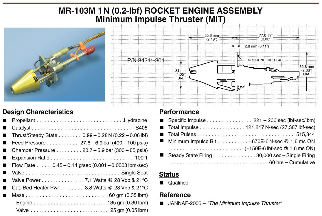
Figure 6*
*Unfortunately, the published specifications for the MR-103H are unavailable. However, the MIT is very similar, and hence shown.

Figure 7
Propellant Tank Specifications
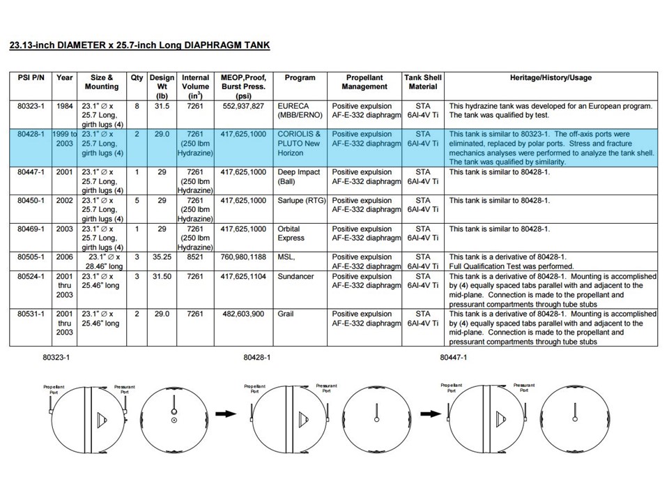
Figure 8
Design advantages
Rather than going through the trade studies for every liquid propulsion system component, I’ll briefly summarize the advantages for the major design components. Although disadvantages are inherent in these components—and very important to consider in trade studies—they are not listed. Many spacecraft missions have used a monopropellant hydrazine liquid propulsion system with a blowdown mode and a diaphragm tank, including Landsat, HEAO, Voyager, IUS, and Magellan. The MR-103H thrusters were used on the Voyager, Deep Impact, and Cassini missions. All of the design decisions for New Horizons revolve around the long mission lifetime, and low-mass considerations. Reliability of the propulsion system components was critical for mission success.
Liquid propulsion system: Why monopropellant?
- Simple, reliable, and low-cost
- No oxidizer system
- Higher specific impulse than cold-gas
- Offers high pointing accuracy
- Less complexity and less expensive than bipropellant
- Pulsing mode capability
Monopropellant fuel: Why hydrazine?
- Relatively easy handling
- Low self-decomposition rate
- Good material compatibility
- Highest specific impulse of the stable monopropellants
- Can be stored in tanks for decades without loss of purity
- Clean exhaust (plume contamination)
- Low flame temperature
Propellant feed system: Why blowdown mode?
- Reduced complexity
- Reduced tank storage volume (single tank for propellant and gas)
- Increased reliability
Propellant tank: Why metallic diaphragm?
- High volume efficiency
- Good center of gravity control
- No sliding seals
- Reliable
- Able to hinder sloshing
- Easily loaded and unloaded on ground
- Ribs on inside improve expulsion efficiency (up to 99.5% guaranteed)
- Long-term storage with near-zero permeation rate
- Hydrazine compatible
New Horizons’ Propulsion System Schematic
The titanium propellant/pressurant tank feeds the thrusters through a propellant filter, a flow control orifice, and a set of latch valves that prevent flow of the fuel until commanded to the open position after launch. The blowdown system provides the pressure gradient to flow the propellant from the tank to the thrusters. Helium was selected as the tank pressurant instead of nitrogen (Figure 9 is labeled incorrectly) to allow the loading of an additional kilogram of hydrazine. The helium’s gas volume (ullage volume) is about 30% of the tank volume. After going through the latch valve, the fuel will continue on to the desired thrusters, which all have their own independent solenoid valve for flow rate control. An extra description of the mechanics through the thrusters is provided at the end.
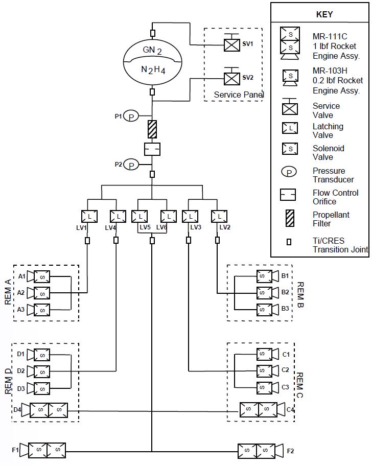
Figure 9
A quick definition on some of the legend keys, as well as their purpose:
- Service Valve—used for filling/draining the tank before launch. Two service valves are required, one before (used for inserting the propellant and pressurized gas) and one after the diaphragm tank (used for draining the fluid, if requested).
- Pressure Transducer—just a pressure sensor, which converts an analog signal (typically a strain measurement converted to pressure) into a digital signal. Using two transducers in different locations, the pressure difference can be determined.
- Propellant Filter—a high or low pressure filtration system for the propellant and pressurant, used to catch any dirt, particles, or debris in the propellant which could block the flow in valves and injectors. Hence, it is the first component below the propellant tank.
- Flow Control Orifice—allows for desired (constant) fuel flow rate via adjustable pressure drops. The calibration is acquired with the pressure transducers before and after the orifice. These are not injection orifices.
- Ti/CRES Transition Joint—a joint between two dissimilar metals. Ti is titanium, and CRES is corrosion resistant steel.
- Latching Valve—essentially a switch valve for flow control; a valve which stays in whatever position it was last commended (open or close). These valves are only opened during planned ΔV maneuvers, and then closed after the maneuver(s) is preformed. During the mission, they may only be 20-50 cycles, depending on the number of TCMs preformed before and after the Pluto encounter.
- Solenoid Valve—controls the propellant flow rate to fire the thrusters. Each thruster has an independent solenoid valve, and approximately 200,000 cycles to each thruster valve is estimated for this mission. Since TCMs are pulsed (~5 ms), and may take up to 15 minutes in order to accumulate the requested ΔV maneuver, it’s obvious that each TCM may require hundreds or thousands of cycles per thruster.
8 of the 16 thrusters aboard New Horizons are considered the primary set; the other 8 comprise the backup (redundant) set. Non-redundant components for the propulsion system includes the propulsion tank, propellant line filter, and the control orifice. Every non-redundant system must have a robust design, and a long history of failure-free service. Limited-life propulsion system components include latch valves and solenoid valves, and must be guaranteed survival throughout the primary, and extended, mission duration.
The thrusters F1 and F2 have a parallel redundancy in their latch valves, which essentially eliminates failure to open. Also note that the larger 4.4N thrusters have series redundancy in their solenoid valves. This significantly reduces the probability of leakage.
Why are the thrusters placed in groups?
14 of the 16 thrusters are grouped in 4 rocket engine modules (REMs). Noticing that the A and D thrusters are on the same side of the spacecraft, and the B and C thrusters are on the other side, the propulsion system is split into two pairs. Each pair of modules share common plumbing to reduce mass and save room.
Why 16 total thrusters?
For 3-axis attitude control, 12 thrusters are required (shown as red vectors). In order to perform transitional maneuvers on the ±Y axis, 4 additional thrusters (shown as blue vectors) are required.
Why are the thrusters used in pulse width modulation mode?
The thrusters are used in a pulse width modulation mode to achieve the desired control precision to execute the slews to targets, and to point or scan the desired instrument toward or across the target. The pulse duration and total on-time of each thruster are commanded very precisely, providing accurate control of the total impulse generated during a maneuver. The 0.8N thrusters have a minimum pulse width available of 5 ms, a value set by design based on the actuation time constants of the thruster control valves. A typical pulse width is shown in Figure 10.
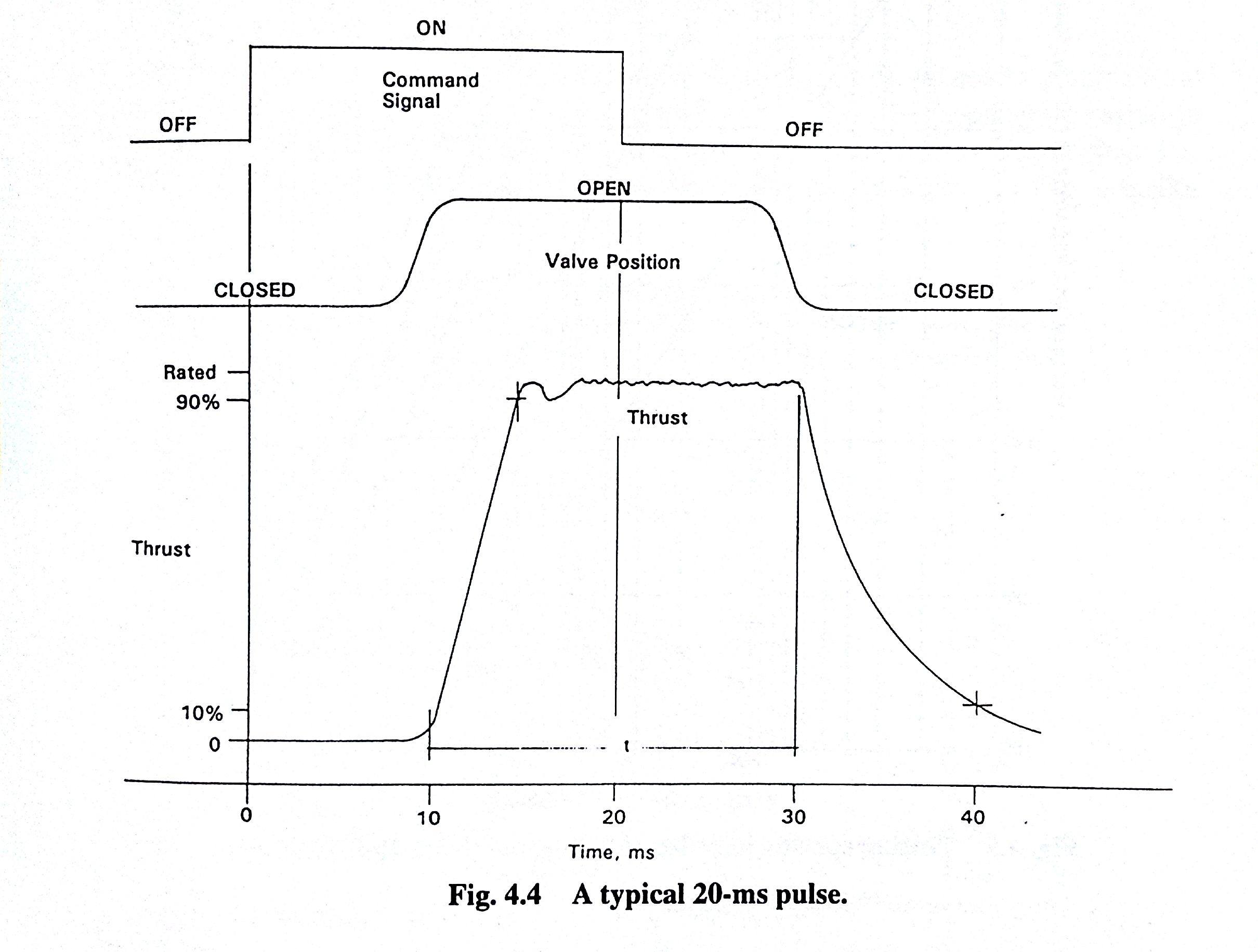
Figure 10
The guidance and control system is capable of providing spin axis attitude knowledge of the spacecraft to better than ±471 μrad (3σ) and spin phase angle knowledge within ±5.3 mrad (3σ). The same ±471 μrad knowledge (3σ) is provided for all axes when the spacecraft is in 3-axis mode. The control algorithms must maintain the spacecraft attitude to within ±24 μrad (3σ) and the spacecraft rotational rate to within ±34 μrad/s (3σ).
MR-103H Thruster Testing
One of the most significant disadvantages of the blowdown mode is that as propellant is used, the pressure in the tank will drop. Pressure determines how much and how fast the fluid moves from the tank to the thrusters. This beginning-of-life pressure will range from 300-400 psi (maximum operating pressure), but drop down to 100 psi at end-of-life (minimum operating pressure). As a result, the Isp and thrust produced decreases as a function of time. Thus, the thrusters have to be capable of reliable, and efficient, operation over a pressure range of 4:1, the so-called blow-down ratio.
The blowdown curves, over the expected temperature range at Pluto, are shown in Figure 11. Once again, as a result of the blowdown mode, the thrust and specific impulse of the thrusters will both drop as the pressure decreases. system. It desirable to maximize the pressurant load and maximum expecting operating pressure (MEOP), thereby maximizing thruster performance. However, the thrusters are required to deliver a minimum impulse bit no greater than 0.0066 N-s during the planned Pluto/Charon encounter, which drives the decision toward a lower MEOP.
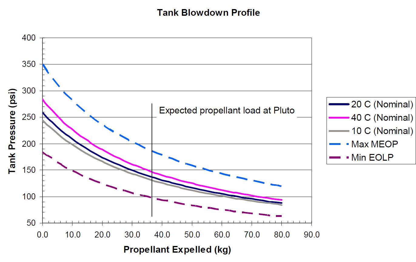
Figure 11
The MR-103H is currently qualified to operate between 420 psia and 80 psia, and can be operated with command pulse widths as low as 4 ms. The MR-103H produces a nominal impulse bit of 0.0066 N-s at 240 psia feed pressure and 0.0040 N-s at 100 psia feed pressure, and is capable of producing impulse bits as low as 0.0026 N-s at 100 psia and 4 ms commanded on-time. The nominal thrust curves for the thrusters over the New Horizons blowdown pressure range are given below in Figure 12.
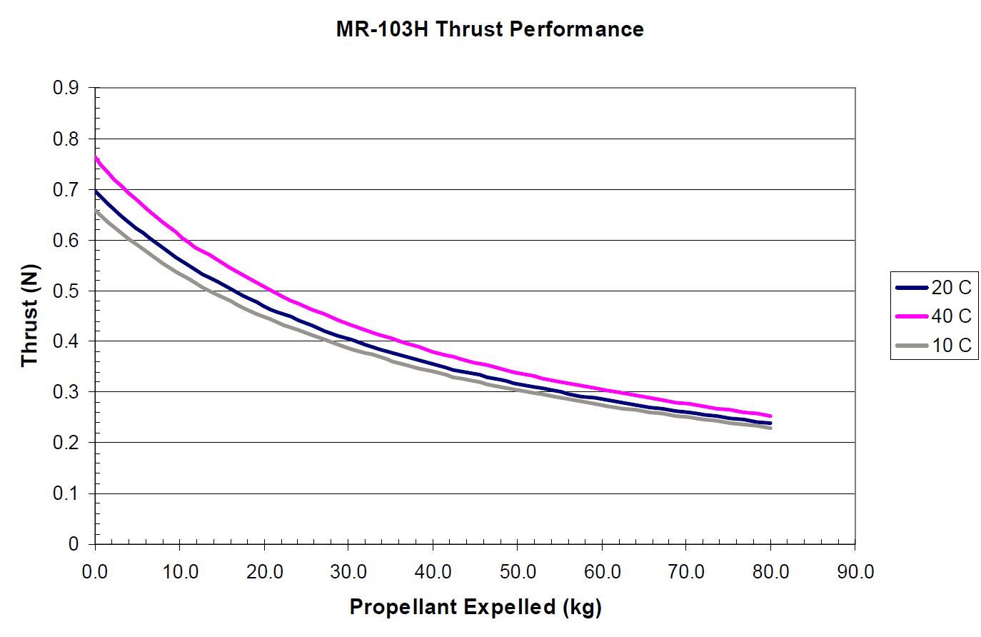
Figure 12
Thruster cycles
The thruster valve cycle limit of 273,000 was adopted from the limit used on the Cassini program. This limit was derived from qualification tests, which demonstrated performance beyond 409,000 cycles. The Voyager spacecraft, which experienced its only failure at over 500,000 cycles, provides valuable inflight data to increase confidence in the thruster valve cycle performance. New Horizons plans to cycle each thruster valve approximately 200,000 times, well under the 273,000 cycle limit. With one exception, the Voyager thrusters continue to operate successfully, after 27 years in operation. The worst-case thruster cycles are provided in Figure 13 with a comparison to the Voyager mission.

Figure 13
What are thruster duty cycles?
The duty cycle is the duration of a pulse (the pulse width) divided by the time between pulses, represented as a percentage. A smaller duty cycle represents a shorter burn, while a larger duty cycle is a longer burn. A 50% duty cycle means, on average, the thruster is on for half of the specified period time, and off for the other half. The cycle life is the number of on/off cycles that the pulsed thruster is able to operate within. For New Horizons, most of the duty cycles are in the 0.1-10% range. For a command on-time of 5 ms, this represents an off-time in the range of 0.05 to 5 seconds between pulses.
Extra: the Hydrazine Thruster
In case you were wondering what happens when the fuel reaches the thruster (shown in Figure 14), below is an excerpt from the Handbook of Space Technology which provides a short description of this process. Yup, this is rocket science.
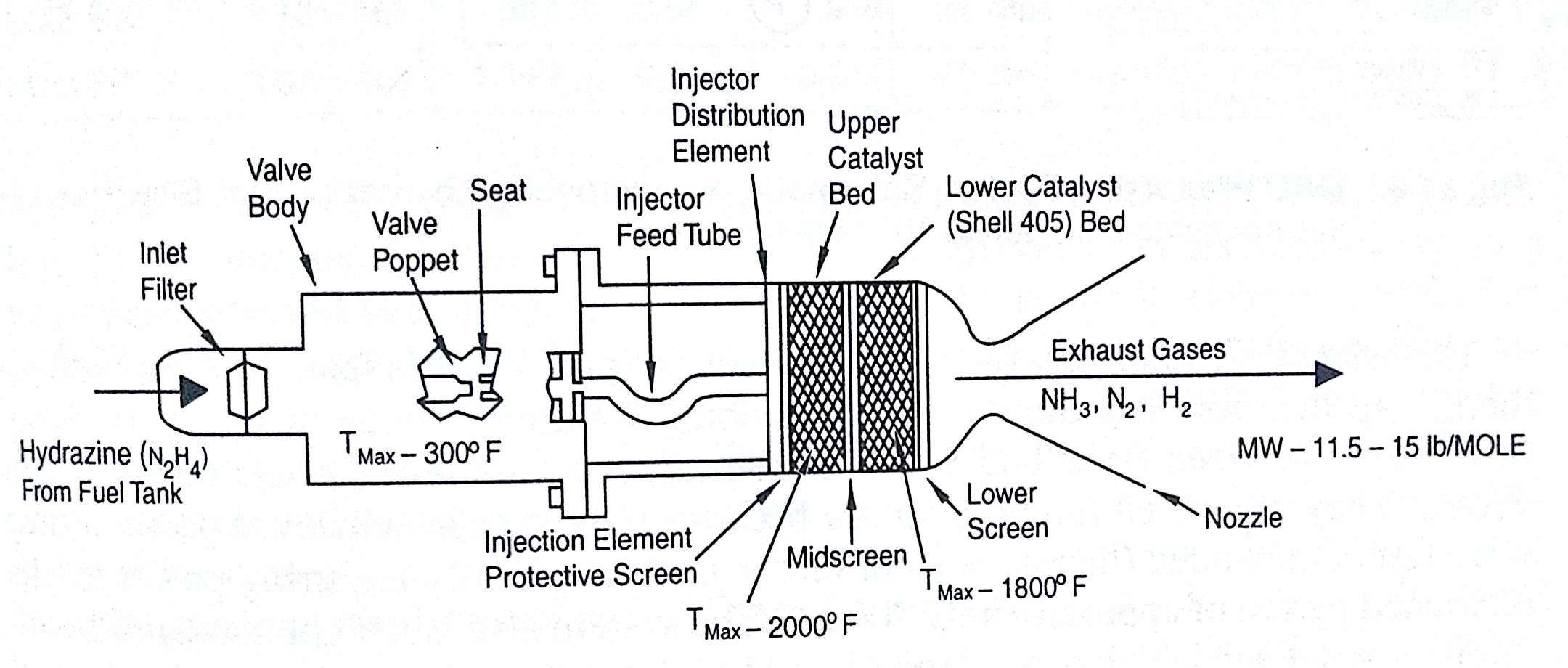
Figure 14
Upon opening the solenoid valve – the flow control valve – the propellant hydrazine passes the capillary tube into the injection head. For engines with a very low thrust level, this capillary tube has a very low internal diameter of 0.1 to 0.2 mm and is bent in an S-shape or even a complete coil. This supports the flow calibration and gives the tube a certain flexibility to overcome stresses induced by the severe temperature gradients between the inlet side and the injector head. The capillary tube is fixed to the heat barrier on the left and to the injection head on the right by high-temperature brazing or welding in vacuum.The complete unit consisting of heat barrier, capillary tube and injection head is subjected to a flow calibration in order to achieve a thrust level tolerance of ±3%. A possible method is to reduce the cross-section of the capillary tube in the crimp area by means of a special tool. Simultaneously the flow rate is measured and the process is completed as soon as the predefined flow rate has been achieved.The configuration of the injection head of the thruster looks like a showerhead with several injection bores and forms an integral part of the injector plate. These bores are equally spaced, so that when the injected propellant hits the front of the catalyst bed it is as uniformly distributed as possible. Injection head and catalyst bed are separated by a hemispherical screen. This screen and the appropriate location of the bores prevent catalyst fines from entering and blocking one or more of these bores.The thruster has two catalyst beds of different grain sizes, which again are separated by an appropriately sized screen. The grains in the first catalyst bed where the decomposition of the liquid or partially evaporated hydrazine takes place are slightly larger, in the order of < 1.0 mm, while the grains in the second bed are smaller, < 0.7 mm. In the second catalyst bed the decomposition of the hydrazine is completed, but the partial dissociation of ammonia also takes place. For the dimensioning of the catalyst beds a possible degradation has to be considered, in particular the reduction of the active surface of the upstream bed during the mission. The decomposition front will move toward the middle screen. The length of the downstream bed can therefore not only be sized on the basis of a minimization of the ammonia dissociation (as short as possible), but also take the functional lifetime and the mission duration into account.During thruster operation, the maximum decomposition chamber temperature can be in the order of [1800 °F]. The decomposition products expand through the bell-shaped nozzle depending on the operational case, the steady-state or pulse mode, [producing thrust].
References:
The Use of the Aerojet MR-103H Thruster on the New Horizons Mission to Pluto
In-Space Performance of New Horizons’ Propulsion System
Autonomous Safeing and Fault Protection for the New Horizons Mission to Pluto
New Horizons Mission Design for the Pluto-Kuiper Belt Mission
A Description of the Pluto-bound New Horizons Spacecraft
Aerojet Data Sheet: Monopropellant Rocket Engines
Orbital ATK Diaphragm Tank Data Sheet: P/N 80428-1
Bibliography:
Brown, C.D. (1996), Spacecraft Propulsion: [AMAZON]
Humble, R. W., Henry, G. N., and Larson, W. J. (1995), Space Propulsion Analysis and Design: [AMAZON]
Larson, W. J. and Wertz, J. R. (1999), Space Mission Analysis and Design: [AMAZON]
Ley, W., Wittmann, K., and Hallmann, W. (2009) Handbook of Space Technology: [AMAZON]
Sutton, G. P. and Biblarz, O. (2010), Rocket Propulsion Elements : [AMAZON]
