New Horizons is voyaging into the coldest depths of space. The solar energy at Pluto is on the order of 1/1000 of the irradiance received in Earth orbit, and will continue to drop as the spacecraft travels into the uncharted Kuiper Belt. An “ideal sphere” spacecraft (Sputnik-looking) would reach an equilibrium temperature of -230 °C at Pluto; the same spacecraft would be 6 °C at Earth. With no adequate external source of thermal energy, New Horizons must be able to internally supply and distribute heat in order to stay within its specified operating temperature ranges.

Figure 1: Spacecraft System Diagram
The burden of the thermal control system is to ensure that the temperature of the spacecraft’s components (especially the payload instruments) are maintained at safe operating levels during the entire mission, in order to prevent component damage. The system is also responsible for taking into account the thermal distortion (expansion and contraction) of materials, which can lead to alignment issues in sensitive instruments.
Despite the spacecraft system diagram depiction of thermal control as a relatively small subsystem (highlighted with a red box in Figure 1), thermal control hardware is vaguely integrated into most subsystems, including propulsion, power, and communications. Thermal control is so important that the control system is independent of the main spacecraft computer, and thus is capable of operating properly even in safe modes.
 Figure 2: Thermos Bottle
If you make coffee before driving to work, you certainly want the coffee to remain hot upon arrival. To do so you use a thermos bottle, also known as a vacuum flask. These containers are able to retain heat using the physics referenced in Figure 2. The approach taken by New Horizons is to retain heat like a thermos bottle—the spacecraft is already in the vacuum of space where no conductive and convective heat transfer will take place, leaving only radiation transfer. By wrapping the entire spacecraft in a multilayer insulation, radiation dissipation is retarded.
The spacecraft subsystems are contained within the thermos bottle-like core of the spacecraft. This thermal design balances the power and waste heat provided by the RTG and electronics, and the natural heat loss through the thermal blankets, structures, and thermal control hardware to ensure each of the system elements remains within safe operating temperatures. The thermos bottle design ties all the subsystems and components to the bulk spacecraft temperature, which remains in the range of 10 to 30 °C throughout the mission duration. This simplifies the thermal control system by focusing on the total power of the spacecraft, rather than localized areas with different temperature requirements.

Figure 3: TerraSAR-X Spacecraft Component Temperature Ranges
Although Figure 3 shows the operational temperature ranges of items on the TerraSAR-X satellite, it provides a great visualization of the specific component-reliance on the thermal design of a spacecraft. The black bar shows the predicted temperature range, the white area represents the allowable temperature range, and the green tips are the uncertainty. In order for New Horizons’ thermos bottle design to work, all the black bars need to be aligned in the 10-30 °C boundary.
Radioisotope Thermoelectric Generator
Because of the low solar irradiance at Pluto (not enough for solar array power, and lack of radiation heating), it was necessary to combine the thermal and power management functions to simplify the overall design, saving both mass and power. A single radioisotope thermoelectric generator (the “F8 GPHS-RTG” supplied by the Department of Energy) on New Horizons provides a total electrical energy available, at the Pluto encounter, of approximately 200 W to operate the spacecraft’s electronics. At launch, the RTG was generating an extraordinary amount of energy, nearly 4,000 W, which had to be radiated into space in order to avoid overheating. This lead to a common problem in spacecraft thermal design: the spacecraft must be able to properly manage extreme ranges in temperature.
Energy has many forms, including chemical (propulsion), electrical, thermal (heat), kinetic (movement), and potential (gravity). Although the RTG is a power source, not a heater, it contributes to the thermal management of the spacecraft with waste heat—a result of thermoelectric conversion inefficacy, hence the “waste.” Approximately 15 W of the waste heat from the RTG is utilized for internal heating. On the other hand, internal electrical energy from the instruments can account for nearly 100 W of dissipated heat
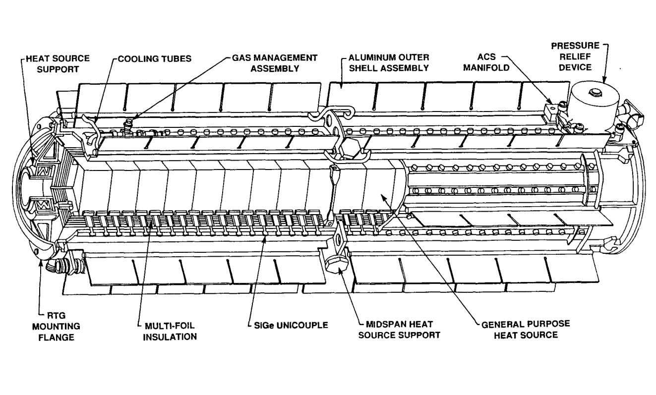
Figure 4: GPHS-RTG
The RTG is supported by a low thermal conductivity titanium support structure. Due to the high stiffness requirement of this truss, cooling fins were added to the RTG adapter collar in order to increase thermal radiation, and thereby prevent material weakening from excess heat. An additional benefit of the RTG placement is that the heat from the RTG can be utilized to keep the propellant from freezing.
Thermal Control Hardware
Radiation is the only mechanism in which the spacecraft can transfer energy into the vacuum of space. Since heat is primarily in the infrared spectrum, a surface with a high infrared emissivity will be able to maximize heat radiation into space. Radiators, shunts, and louvers—all of which are similar in purpose, but different in design—take advantage of this. Radiators are the simplest of these three systems since there’s no software management; they are always radiating infrared radiation, there’s no on-or-off. The placement is obvious: if an electronic is continuously producing excess heat when on, then a radiator is placed near it.
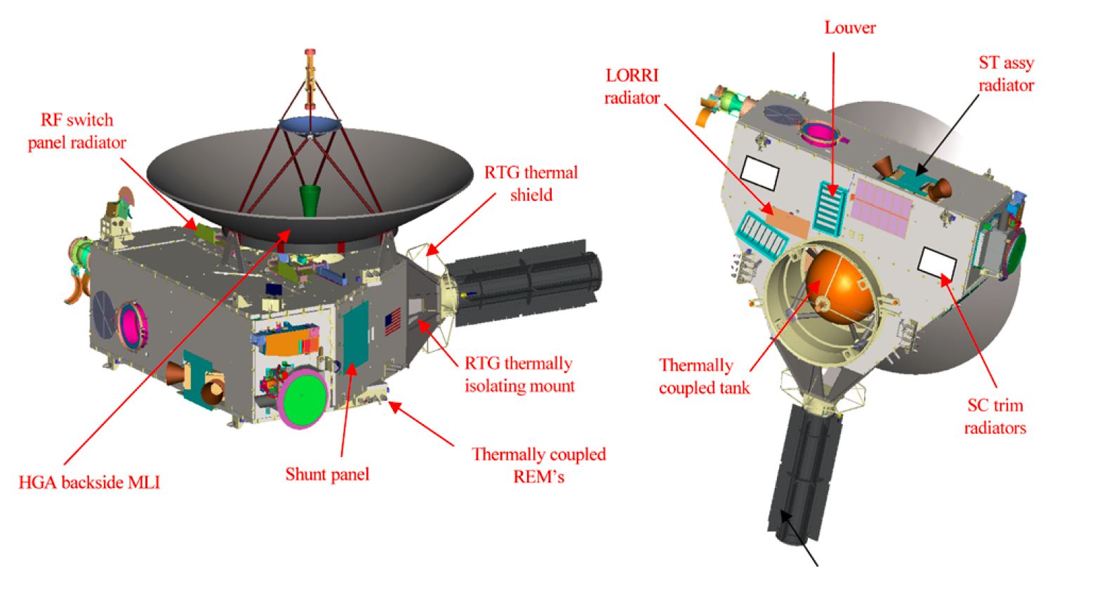
Figure 5: Highlighted Thermal Design Components
When the RTG is producing excess energy (exceeding 30 V), external resistive shunts will transform the electricity into heat via resistors. The shunts are sized to reject the RTG maximum power produces while at Earth, where the spacecraft also encounters its maximum thermal radiation. Visible in the featured image and Figure 8, the shunts are the large, white flat-plates on the exterior of the structure. The white surface finish helps to maximize heat rejection, and minimize heat absorption.
Similarly, louvers are used to dissipate excess heat, typically from running too many instruments. Louvers are located on the belly side of the spacecraft, visible in Figure 8. Resembling Venetian blinds, the louvers will radiate heat when open, and reflect heat when closed. As a rule of thumb, louvers reject six times as much heat in the open position as it does in the closed position. These thermal louvers actuate if the internal temperature exceeds 25°C.
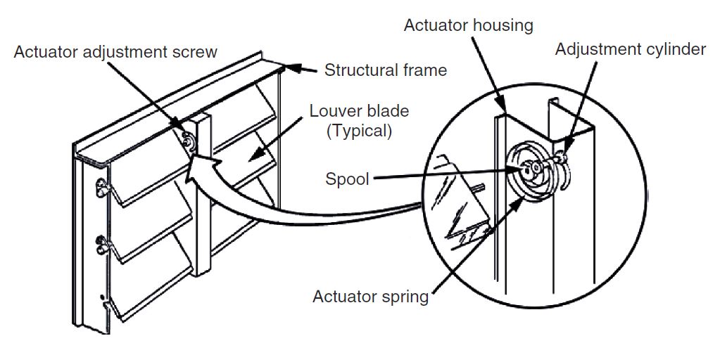
Figure 6: Louver Assembly
As a result of the cold environment, active heaters are required. There are 2.5 W, 5 W, 10 W, and 20 W heaters spread around the spacecraft. The sophisticated, automated heater control software monitors the power dissipated in the spacecraft and turns on various heaters to maintain safe temperatures. Any drop below an operating level of about 150 W will activate the heaters.
The long, slender rods attached to the propellant tank are conduction isolators, made of a low-conductivity material. These isolators are most likely (guessing) for the propellant line support, not to decouple the tank from the whole thermal system. Since propellant lines are thin and rigid, they are sensitive to thermal shock and deformations. Because the electronics and hydrazine fuel can remain within the same operational temperature range (10 to 30 °C), it is beneficial to thermally couple them. The only thermally uncoupled systems on New Horizons is the high gain antenna, and the star trackers.
Multilayer Insulation
Multilayer insulation (MLI) blankets can be found surrounding nearly every spacecraft, and provide the thermos bottle effect. The complex layering system, shown in Figure 7, prevents both excessive heating and heat loss. The blankets are designed to retain the thermal radiation emitted inside the spacecraft bus, mainly waste heat from electronics, to sustain an operating temperature between 10 and 30 °C. Because MLI absorbs radio waves, it is not placed on the antenna dish. These blankets also protect the spacecraft’s bus from micrometeorites.
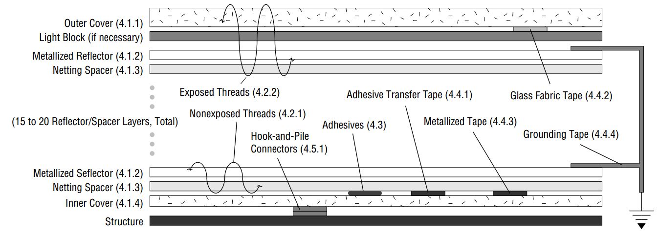
Figure 7: MLI Composition
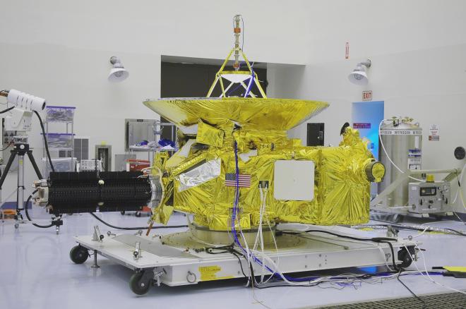
Why is the spacecraft gold? Because of the MLI: the outer layer is aluminized Kapton, a transparent film with an amber tint; the silvery-color aluminum on its backside gives the impression of metallic gold from the front. MLI does not contain gold itself, it’s simply the combination of Kapton (transparent amber) and aluminum (shiny silver) which gives the illusion of gold.
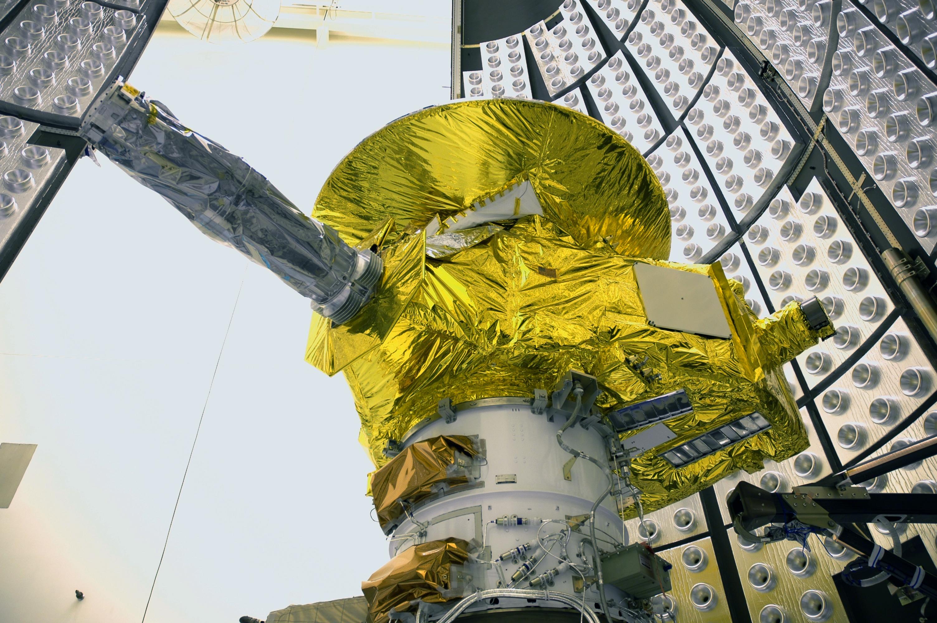
Figure 8: New Horizons with MLI Installed
